|
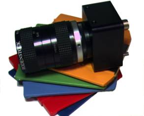
SI-640HF
Trigger & Readout Modes
The SI-640HF VGA High-Speed Freeze-Fame
Shutter camera captures images of fast moving objects by starting
integration simultaneously on all pixels and then stopping integration
simultaneously. The resulting charge on each pixel is then sampled into
pixel analog memories (one memory per pixel).
Then, row-by-row, the pixels are digitized and read out-of-sensor
and transmitted over the digital interface.
The
camera operates in three Capture Modes
-
Triggered Snapshot:
Camera accepts an external trigger, exposes
the full frame and then outputs the valid image.
-
Continuous Snapshot:
No external trigger is required and the snapshot-exposed images
are output continuously.
-
Live Video:
Live video is continuous output
with overlapping frame shutters exposures and readout.
The Live video mode is the fastest mode for
free running (non-triggered) operation. Multiple SI-640HF cameras can be
synchronized to run using an optional external sync and pixel clock lock
(-X option)
Triggered Snapshot (Mode
1)
In
triggered snapshot mode, the camera accepts an external trigger (software
or hardware driven) exposes the image and generates the readout. The
integration time is programmed through the cameralink serial interface
(Register 9). The trigger can
be generated by serial character over the cameralink interface, a CC-1
Hardware trigger on cameralink, or TTL-Trigger directly into the camera.
Snapshot
mode can be used to capture a single image or a sequence of images.
Changing the period of EXPOSE trigger pulses controls the snapshot rate
(frame rate).
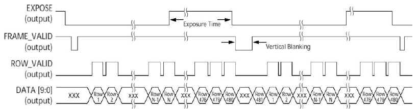
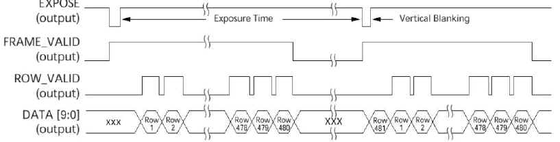
When the camera begins readout the
FRAME_VALID, ROW_VALID, and DATA signals are output.
The FRAME_VALID (FVAL) signal goes HIGH, indicating the start of
frame, and 2.5 clock cycles later the ROW_VALID (LVAL/DVAL) signal goes
HIGH, indicating the start of the first row.
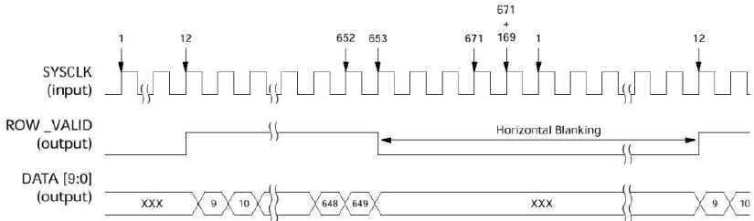
The time required for one complete row
operation is always 671 clock cycles.
ROW_VALID will be active high for the 640 (default) columns of
valid data. With a master clock of 66 MHz, this translates into a row time
of 10.2µs and a frame time of 5.1ms for full resolution (502 rows).
This assumes there is no vertical blanking or horizontal blanking
and that the exposure time is less than 4.9ms. If exposure time becomes
greater than 4.9ms, the frame time is set by the exposure time and the
rate becomes the inverse of the exposure time (1/[exposure time]).
Triggered
Snapshot - Row Timing
Triggered
Snapshot - Frame Timing

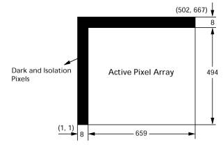
The default register settings program the
imager to read out the first 640 x 480 visible pixels (no black pixels).
Therefore, the start row is 1, start column is 9, end row is 480 and the
end column is 648.
Continuous Snapshot
(Mode 2)
In continuous Snapshot mode, the timing is
identical to triggered mode. However,
in this mode the camera continuously generates snapshot images at the
maximum frame rate, with only a single row time of delay between frames. An external trigger signal does not need to be applied to the
camera. This mode is ideal
for initial system setup for focusing and camera alignment, prior to
having the trigger source and wiring completed.
This mode will show the same image as triggered mode and will
immediately show the maximum possible repeat trigger rate for a specific
clock rate and exposure time.
Live Video (Modes 3)
In Live Video mode full-frame shutter
exposure period occurs simultaneous during readout. This is the fastest
mode of operation since the exposure and readout are happening in parallel
rather than sequentially. The
readout of the data out of the chip can be done simultaneously with
integration and ADC operation due to the unique two-cell SRAM pixel
architecture, which allows data from the previously converted row to be
shifted into the output memory for readout during new frame exposure.
Frame
Timing #1 (readout time >
exposure time)
Frame Timing #2
(exposure time > readout time)
If the exposure time becomes greater than
the image readout time, the maximum frame rate will be set by the exposure
time. The frame rate becomes
the inverse of the exposure time (1/[exposure time]), as seen in Frame
Timing #2.
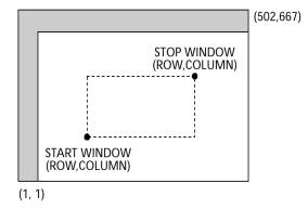
High-Speed
Windowing
There
is also an option to scan just a window of interest by choosing start row
and column and stop row and column. The user can control the frame rate
and row rate through the use of vertical and horizontal blanking as well
as the master clock frequency. The
readout of the data can be done simultaneously with integration and ADC
operation due to the two-cell SRAM pixel which allows data from the
previously converted row to be shifted into the output memory for readout.
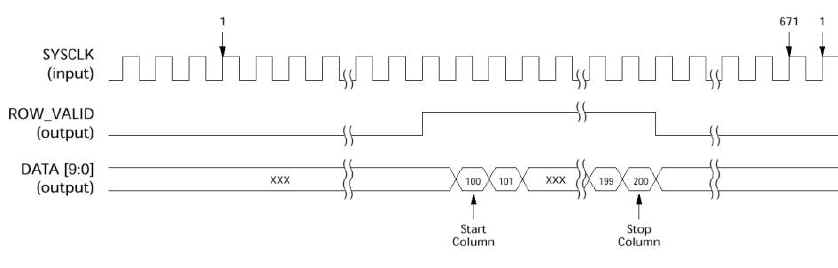
Row
Timing (Window Mode)
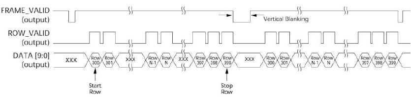
Frame
Timing (Window Mode)
Exposure
& Frame Time
The
integration time is pre-programmed via the Serial Interface and indicated
by the EXPOSE (Strobe Output) signal going HIGH.
The
time required for one complete row operation is always 671 clock cycles.
ROW_VALID will be active high for the 640 (default) columns of
valid data. With a master clock (SYSCLK) of 66 MHz, this translates into a
row time of 10.2µs and a frame time of 5.1ms for full resolution (502
rows). This assumes
there is no vertical blanking or horizontal blanking and that the exposure
time is less than 4.9ms. If exposure time becomes greater than 4.9ms, the
frame time is set by the exposure time and the rate becomes the inverse of
the exposure time (1/[exposure time]).
Row_Time
= 671 Clocks
Height
= Image Rows +
Vertical Blanking Rows (Reg 9: 255 rows
maximum)
Readout_Time
= Row_Time x Height
Frame_Time
= Readout_Time
(Readout time > exposure)
=
Exposure_Time
(Exposure > readout time)
Frame_Rate
= Exposure + Frame_Time
(Snapshot Modes)
= Frame_Time
(Live Mode)
|