|
SI-6600-M & RGB MegaCamera™ 6.6 Megapixel, 10-Bit, 60MHz Ultra-High Resolution Portrait Digital Camera |
Silicon Imaging Inc.
|
||||||||||||||||||||||||||||||||||||||||||||||||||||||||||||||||||||||||||||||||||||||||||||||||||||||||||||||
|
|
|||||||||||||||||||||||||||||||||||||||||||||||||||||||||||||||||||||||||||||||||||||||||||||||||||||||||||||||
|
Silicon Imaging is
proud to continue its innovation in ultra-high resolution machine vision
camera.
Driven by the growing demand for consumer Digital Still Cameras,
CMOS sensors are continuing to break technical barriers and surpass the
performance characteristics of CCD’s in many photonic, imaging and
consumer applications. By
utilizing a single highly integrated CMOS device, which incorporates
Megapixel sensing areas, timing generation, signal processing and high
bandwidth outputs, Silicon Imaging has developed a very compact,
low-power, ultra high speed Megapixel digital camera system. 2210
x 3002 Megapixel - Ultra Resolution 10-Bit
Pixel Sampling – Sub-Pixel Accuracy 1000
FPS - Windowing & Subsampling Dual Slope Exposure - “Super-Dynamic” CameraLinkä
Digital Interfaces GigE-Cameralink – Gigabit Ethernet Connectivity Now you can capture high-speed MegaCamera images to your PC from distance of a 100-meters using CAT-5 wire using the Silicon Imaging GigE-CameraLink Interface. The GigE-Cameralink captures MegaCamera digital images and transmits them via 10/100/1000 Gigabit Ethernet directly to your PC at speeds over 100MB/sec.
|
 |
||||||||||||||||||||||||||||||||||||||||||||||||||||||||||||||||||||||||||||||||||||||||||||||||||||||||||||||
|
|||||||||||||||||||||||||||||||||||||||||||||||||||||||||||||||||||||||||||||||||||||||||||||||||||||||||||||||
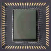
6.6
Megapixel CMOS Image Sensor
The
MegaCamera SI-6600 utilizes a proprietary portrait style 6.6 Million pixel
high-speed CMOS image sensor. Each pixel is 3.5um square, ideal for image processing, and
the entire array fits the 1” format for flexible optic choices.
This reduction in process geometry allows for both an increase in
transistors and fill factor without compromising performance, plus offers more
advanced readout controls, greater speeds and lower power dissipation.
This new sensor technology offers a more responsive pixel design with
added circuitry for increased dynamic range, greater sensitivity, decreased
fixed pattern noise and low dark current for
long exposure applications. Unlike
CCD, which leak charge to adjacent pixels when the registers
overflow (blooms), the SI-6600 provides inherent
anti-blooming protection in each pixel,
so that there is no blooming. The
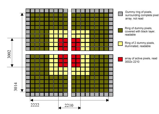
array has 2210 pixels on a line and 3002 rows, which result in a near 3:4
portrait aspect ratio. The SI-6600
outputs 2208 x 2960, using 42 rows for interframe blanking.
The image can be rotated 90-degrees to obtain a 4:3 image. In addition,
by using the windowing feature, a 16:9 aspect ratio (eg. 1280x 720) or 1:1
aspect ratio (1024 x 1024) are available. At smaller ROI sizes (eg. 128 x 128)
frame rates in excess of 1000fps.
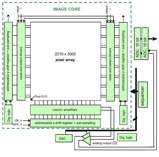
The
SI-6600 MegaCamera achieves high data rates by simultaneously accessing two
adjacent pixels at a time and reading them out sequentially.
These pixel values feed thru a gain & offset amplifier and then to
on-board dual 10-Bit A/D converters and placed onto a 12-bit data bus for
transmission. The entire
imager field of view can also be readout using subsampling.
In this mode, 2 pixels are readout and a group of pixels are skipped.
As fewer pixel are output, the frame rate increases In
a color model, a Bayer filter covers each of the pixels to produce a pattern of
values that represent the color information, which must be processed and
interpolated to obtain an RGB value per pixel.
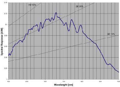
The 12-bit output format from the camera is identical for monochrome and
color models. The camera sensor is light
sensitive between 400 and 1000 nm. The peak QE * FF is 22.5% approximately
between 500 and 700 nm. In view of a fill factor of 35%, the QE is thus close
to 70% between 500 and 700 nm.
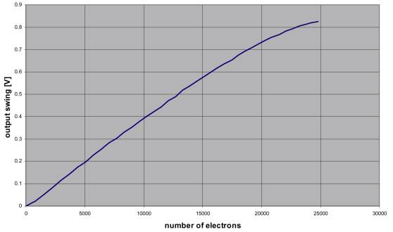
The figure above shows the pixel response curve in linear response mode. This curve is the relation between the electrons detected in the pixel and the output signal. The resulting voltage-electron curve is independent of any parameters (integration time, etc). The voltage to electrons conversion gain is 37 µV/electron. 10-Bit Digital Sampling System A
10-Bit Analog-to-digital (A/D) converter samples each pixel value and quantizes
it into 1024 levels, as it is clocked out of the sensor. Pixel clock sampling ensures precise measurement of the
photonic charge without the jitter and sampling uncertainty associated with
traditional analog video systems, such as RS-170 and CCIR.
The camera produces images which can deliver improved photometry accuracy
and sub-pixel metrology. The use of 10-bit converters versus traditional 8-bit
systems further enhances the image dynamic range.
The combination of 10-bit vertical resolution and pixel clock sampling
provide precise sub-pixel measurement accuracy (ex. 1/10 pixel).
Digital Clock Synthesizer
A
wide range a master clock frequencies (eg. 20 to 60MHz) can by precisely
generated using the Digital Clock Synthesizer. The Frame Grabber, which is
used with the camera, must be capable of receiving 12bit at 60Mhz to
achieve the highest data rates. Without any byte packing of the 12-bit
word the data rate would be 120MHz (2pixel x 2bytes/pixel x 60MHz).
In standard 32Bit/33MHz PCI computers the maximum data rate
directly to host memory is usually below120Mbytes/sec (from 132MB/sec bus)
without system interrupts. However,
100MB/sec is more reasonable rate to achieve with other system devices
operating (eg. display, clock, mouse etc.).
Under these condition the 12-bit data can be mapped to 8-bits/pixel
to reduce the bus traffic or the clock rate can be reduced to and still
maintain 12bits/pixel. The
frequency of the clock synthesizer can be set by serial command. A table with associated clock frequency is found in the
serial programming section of the manual.
Due to minimum frequency restriction on the digital transmission
link, the pixel clock frequency cannot be lower than 20Mhz. Embedded Microprocessor
A microprocessor in the camera provides the control interface between the PC and the functional block in the camera (Sensor, Clock Synthesizer, Register Memory, Channel Link Interface & Serial port (CameraLink). The Microprocessor receives commands thru the LVDS level serial port and issues commands to the other devices. It also can store preset values for camera setting, which can be recalled with single ASCII character commands. Several digital I/O or analog sampling signals are available on the processor from PCB header points for custom OEM applications. 12-Bit CameraLink Interface (Base Configuration) Camera
Link is a new digital transmission method designed by imaging component
manufacturers as an easy and standard way to connect digital cameras to
frame grabbers. The Camera Link specification includes greater than
1.2Gb/sec data transmission as well as camera control and asynchronous
serial communications all on a single cable with high-density 26pin
connector. Only two
connections are required to quickly interface your digital camera to a
multitude of frame grabbers. This
standardization will ultimately reduce cost of high performance digital
cameras through open market competition and a simple migration path to
faster and higher resolution systems. As
a standard that has been defined by industry members, Camera Link provides
the following benefits:
The standard Camera Link cable uses a MDR 26-pin connector (3M Part# 10226-6212VC)provides the following signaling: ·
Video
Data (4 Pairs using 28:4 Mux,
24 Video, 4 Control) ·
Camera control
signals (1 Pair) ·
Serial
communication (2 Pairs) ·
Power (3 pair)
– Optional Control signals 2, 3, 4 The
24 bit image data (2 words x 12 bit) and 4 control bits are transmitted
over only 4 differential pairs using a 28:4 multiplexer (National
Semiconductor DS90CR285 Channel Link
device). The Four enable
signals are defined as: •
FVAL—Frame Valid (FVAL) is defined HIGH for valid lines. •
LVAL—Line Valid (LVAL) is defined HIGH for valid pixels. •
DVAL—Data Valid (DVAL) is defined HIGH when data is valid. •
Spare— A spare has been defined for future use. All
four enables are provided on the camera, via the Channel Link chip. The
unused data bits are tied to a known value by the camera.
For more information on image data bit allocations, see page 11, CameraLink
Base Configuration Bit Assignment Configuration. Two
LVDS pairs have been allocated for asynchronous serial communication to
and from the camera and frame grabber. Cameras and frame grabbers should
support at least 9600 baud. These signals are •
SerTFG—Differential pair with serial communications to the frame
grabber. The
serial interface operates at 9600 baud, one start bit, one stop bit, no
parity, and no handshaking. For
applications requiring high serial throughput, such as real time windowing
update at over 200FPS, the camera can support a serial link mode at 57kbs
(not specified in CameraLink spec). The
frame grabber serial communication must be set to match this speed. Camera
Control Signals & Power Four
LVDS pairs are reserved for general-purpose camera control. They are
defined as camera inputs and frame grabber outputs. Camera manufacturers
can define these signals to meet their needs for a particular product. The
signals are: •
Camera Control 1 (CC1) - Used
to do triggered image capture |
|||||||||||||||||||||||||||||||||||||||||||||||||||||||||||||||||||||||||||||||||||||||||||||||||||||||||||||||
|
SI-6600 Cameralink Manual (PDF 1.5MB) |
|||||||||||||||||||||||||||||||||||||||||||||||||||||||||||||||||||||||||||||||||||||||||||||||||||||||||||||||
|
|||||||||||||||||||||||||||||||||||||||||||||||||||||||||||||||||||||||||||||||||||||||||||||||||||||||||||||||
|
Subsampling Frame Rates
|
|||||||||||||||||||||||||||||||||||||||||||||||||||||||||||||||||||||||||||||||||||||||||||||||||||||||||||||||
|
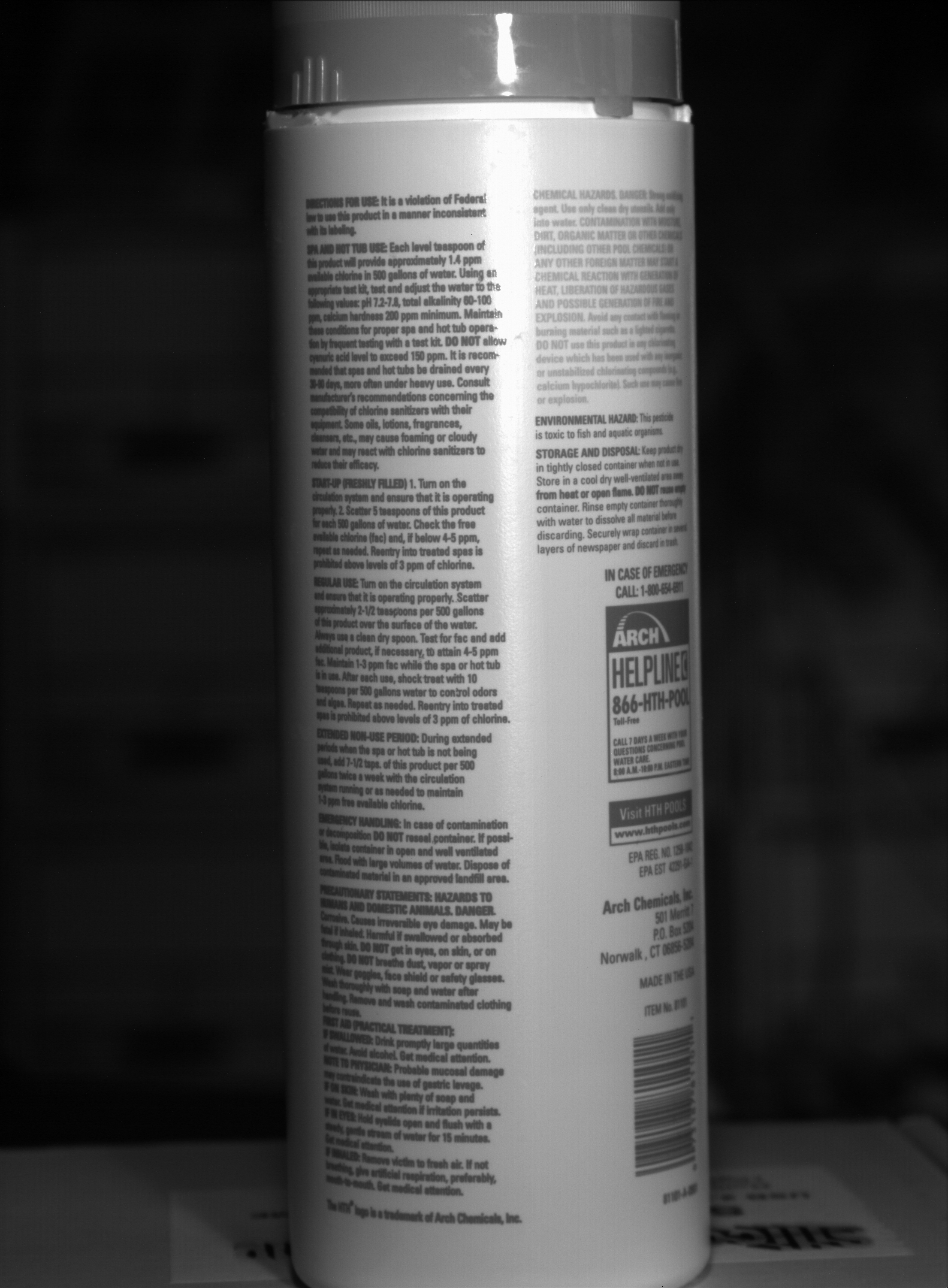
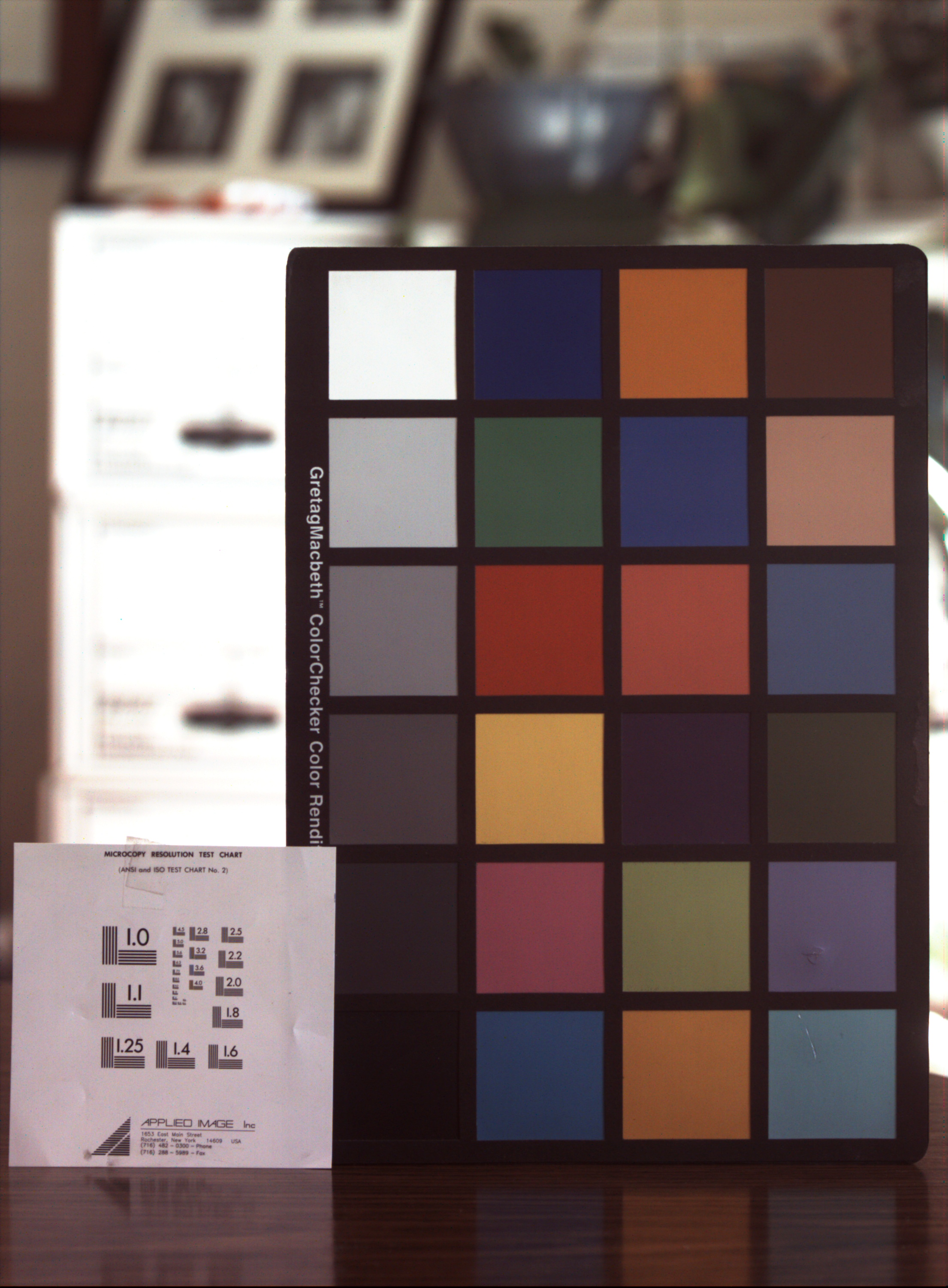
Sample Test Images (2200 x 3000)
|
|||||||||||||||||||||||||||||||||||||||||||||||||||||||||||||||||||||||||||||||||||||||||||||||||||||||||||||||
|
6.6MP Mono Full Size Image- 2.5MB & 1.7MB JPG! (click) |
|||||||||||||||||||||||||||||||||||||||||||||||||||||||||||||||||||||||||||||||||||||||||||||||||||||||||||||||

.jpg)
.jpg)